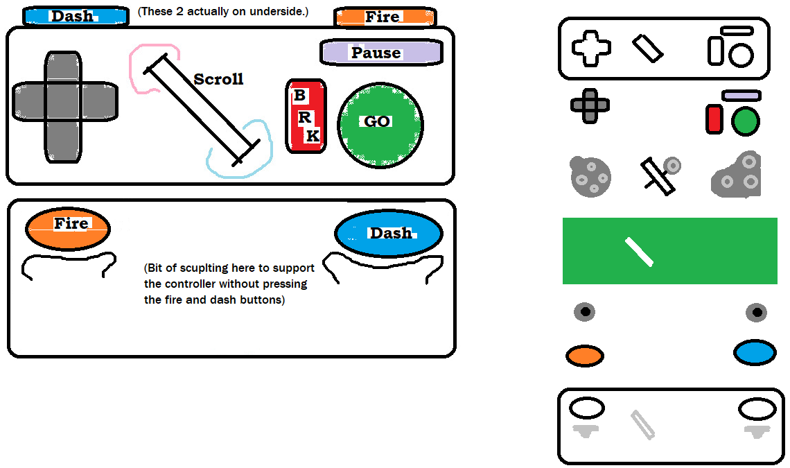
This particular step in this project involves the design of a controller, meant to be compatible with the console I am designing, as well as the NES and SNES (depending on the connector used). The controller will feature a D-pad, 3 face buttons, two additional buttons on the underside of the controller, and a central scrollwheel (which barring complications will also act as a button). A rough, not quite to scale sketch of the controller's appearance and layer by layer assembly is below. Hopefully guidelines can be built into the shell to line all of this up easily. The specific dimensions will largely be determined by how compactly the PCB can be arranged, with the hope of being rather small, to facilitate both reaching the scroll wheel with either thumb, and facilitate the hands of small children. A larger variation may come in the future, along with an alternate hitbox-style design.
A cord connecting the PCB to the console, for all three consoles, features a 7 pin connector, but the standard controllers for the NES SNES (and hopefully this) only actually run 5 wires through it-
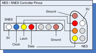
Rather than directly feeding the state of each button back to the console, we have a single data wire, reading from a shift register in the controller. (Documentation link) The NES reads this out as an 8-bit value:
A, B, select, start, up, down, left, right.
SNES reads 16:
B, Y, select, start, up, down, left, right, A, X, L, R, 0,0,0,0
(with those last 4 bits identifying it as a standard controller). It's an abandoned compatibility thing (and I hate how many things emulating NES controls through a 4 face button interface don't follow this). My understanding is a standard mouse scrollwheel outputs a 2-bit Gray code, so IN THEORY if my outputs are
Go, BRK, wheel-A, wheel-B, up, down, left, right, wheel-click, pause, dash, fire, 0,0,0,0
things will MOSTLY map in a pretty intuitive way if someone wants to use one controller as a substitute for another (with the slight problem of having to either rock a scroll wheel ever so slightly to pause or dance a couple fingers across select and start to fake scrolling. These options are VERY MUCH NOT IDEAL, but handy for debugging/emulation/writing SNES software to use this hardware/etc. If you don't know gray code, with 2 bits you're outputting 00 01 11 10 00 to scroll one way, 00 10 11 01 00 for the other. Only changing 1 bit at a time. This is also all assuming I am at all on-base with how these encoders acrually work. Big if, too here's what I have to go off there: (Link) Also this fairly clean look at a daughter board for some custom mouse project:
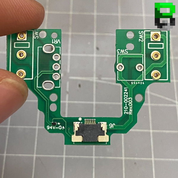
I should really test this before going any further, but... I've got a pile of these the actual rotating bit requires a snug-fitting rod I had a 3D printed component for, but it didn't do the job, and the 3 prongs that matter are an awkward shape people apparently just mash into a PCB and bury in solder. The prong is just extruded from the side of the wheel, which has another axel that just rests on a button so the whole thing can be awkardly pushed at a bad angle for a click, apparently. So... I guess to really properly test this I'd either need some elaborate setup with clamps and keeping the whole thing elevated and getting a better wheel to jam inside (not to mention needing general electonics testing gear I don't presently have access to) so... I dunno, just printing the PCB, jamming it in, and seeing if that works might be cheaper/less of a headache at this point?
So all that said, basically what I need to do is use an SNES controller PCB as a jumping off point, replace the shoulder button daughter boards with back-mounted buttons, rearrange the other buttons a little, carve a big hold through the middle to house a wheel, redirect select start and A, to that, and... work out how to get a nice long cable carrying 5 wires hooked to it (this is actually still one of my big mysteries). Poking around for a good image of the standard SNES controller PCB brought me to an interesting redesign (link) This uses a more modern and apparently better available shift register, connects most of the board surface to ground (which is apparently good practice?) and makes some other changes I am going a bit blurry-eyed trying to find the traces for.
So... I need to work out how to measure out the placement of bridgeable contacts for each button to match up with the replacement membranes I have for a Gamecube controller here (which for now is the cheapest fix I can find for getting the ones I need) and also decide which face button contact I'm slicing off. I need to work out what I'm using for a cord. And... I need to work out what sort of software and PCB manufacturer I need to get an initial prototype board going. Plus I need to jam a mouse scrollwheel in somehow. And I wouldn't mind any other design tips from people more experienced with this sort of thing.